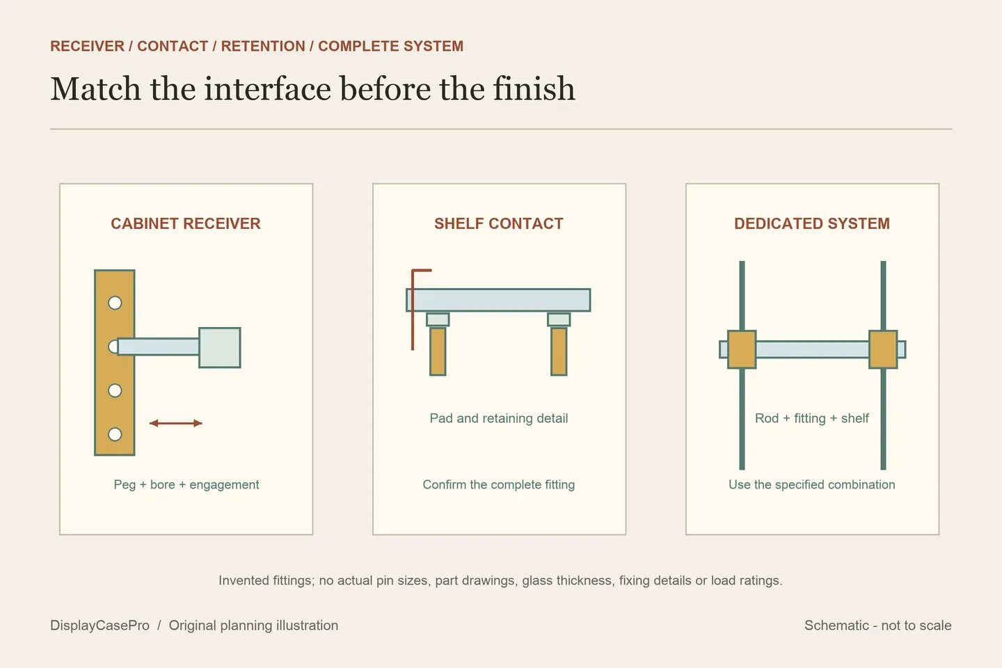
Choose display cabinet shelf supports by matching the cabinet’s existing interface first: a pin bore, rail, retained clip or dedicated rod system. Then check the shelf material, contact surface, retention and exact part. A matching finish or a pack labelled “shelf supports” cannot establish compatibility with your cabinet.
Identify the part before choosing its replacement
Find the cabinet model, assembly instructions and any support part number. With the shelf unloaded and handled as its maker directs, record the existing fitting’s shape, location and release method. Keep an intact reference part where available; photograph its contact surface and how it engages the cabinet.
Distinguish a support that plugs into a side-wall bore from a clip fitted to a rail, a clamping glass support or a fitting carried by a vertical rod. Those interfaces need different records. The small seat locating a collectible or shot glass is also different from the hole that receives a cabinet shelf pin.
If the receiving hole or surrounding structure is damaged, ask the maker about the repair before buying a larger pin. A part that can be pushed into an opening is not necessarily the specified replacement, and color does not identify its engagement or retention method.
The original categories cover several incompatible systems
These original sources were read on 19 October 2026. They establish product families and published part descriptions, not measured compatibility, tested capacities or a ranked shortlist. A category containing both wood and glass fittings does not make every item suitable for both materials.
| Source | Observed distinctions | What still needs confirming |
|---|---|---|
| Peter Meier | Single-peg, two-peg, glass, plastic and concealed supports. | The actual part’s peg, contact surface and intended shelf. |
| Häfele | Wood and glass supports, several pin sizes, pilaster and bracket systems. | The exact item and its installation and load conditions. |
| Lyons Hardware Tree | Plain pins, covered glass rests, locking supports, adhesive pads and wall brackets. | Which pieces carry, cushion or retain the shelf in your assembly. |
| Woodworker Express | 5 mm and 1/4 inch bores; clamping glass fittings and clips for specified shelf thicknesses. | Bore size, shelf material and thickness, part number and pack quantity. |
| Nova Display Systems | Panel and shelf fittings for a dedicated 6 mm rod system. | Rod, fitting, shelf and fasteners as one specified combination. |
Häfele’s category showed glass-specific items alongside wood supports, hold-downs and wall brackets. Its generic category labels do not provide the full installation conditions for a selected part. Likewise, a capacity number on a card or filter should lead to the technical specification, rather than becoming an assumed rating for every support in the category.
Match the bore and the pin independently of the shelf thickness
A 5 mm pin and a 1/4 inch pin are different nominal sizes: 1/4 inch equals 6.35 mm. Keep the original units and specification instead of rounding both to the same metric label. Also record pin length, shape and engagement details supplied for the actual part.
The Peter Meier DREAM glass shelf support, item 02.7850.101, specifies a ribbed 5 mm peg, a steel pin body and a neoprene top surface. It says the supports are sold individually and packed 1,000 per box. The peg size describes the cabinet interface; it is not the shelf’s glass thickness or a verified load allowance.
For a two-peg fitting, record both the peg size and their spacing. For a socket or sleeve arrangement, identify the mating receiver too. Do not substitute overall fitting length for pin engagement, or infer a missing dimension from a photograph. Ask for the part drawing when the receiving geometry is unclear.
Glass contact, shelf retention and the bearing surface are separate
| Detail | Its role | Check against |
|---|---|---|
| Pin or peg | Engages the cabinet’s intended receiver. | Specified bore, engagement, shape and condition. |
| Pad, cap or covered rest | Provides the specified contact surface beneath the shelf. | Actual shelf material and complete support part. |
| Clip or clamp | Retains the shelf in the way the fitting is designed to work. | Material, thickness range and normal release instructions. |
| Bearing height and projection | Locate the supported shelf surface relative to the cabinet. | The matched fittings and permitted support positions. |
Woodworker Express lists locking clips for different shelf thicknesses, including 1/2, 5/8 and 3/4 inch material, alongside separate clamping glass supports. A clip that fits a wood-shelf thickness is not thereby approved for an equally thick glass shelf. Confirm the complete item’s intended material and contact arrangement.
Similarly, an adhesive bumper or replacement cap is not automatically a complete load-bearing support. Keep the pad, underlying fitting and retention method identified together. Ask about missing or deteriorated contact pieces rather than stacking improvised pads to alter the shelf level.
Wall brackets and rod fittings require their own installation records
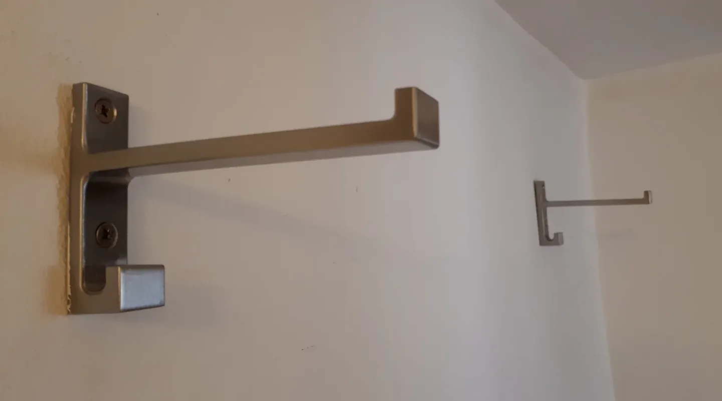

The photograph illustrates a different mounting interface. A wall bracket’s projection and fixing pattern need their own specification; it cannot be substituted for a push-in cabinet support merely because both support shelves. The image does not identify the pictured fittings as any product in the comparison.
Nova’s category is specifically for 6 mm rods. Its RG06 shelf-support description allows shelves up to 7 mm thick, while RS01 describes a drilled or slotted shelf with a 10 mm hole. The rod diameter, shelf thickness and shelf-hole size describe different interfaces. They are not interchangeable dimensions for a cabinet pin.
Keep the exact fastener combination as well. Nova’s RG12 heading describes panels up to 7 mm, but its detailed note says the included standard set screws hold 3–6 mm substrates and calls for suitable replacements outside that range. Confirm the selected system’s instructions rather than treating the headline maximum as complete compatibility.
Confirm the matched assembly and the quantity being ordered
Save the cabinet model, part number, receiver, shelf material and thickness, contact pieces, retention method, support positions and order unit. A price per piece and a pack quantity answer different questions. Confirm how many complete matched fittings are supplied and what accessories are included.
Obtain the maker’s permitted loading conditions for the complete assembly, including shelf, contents and other display supports. Do not multiply an isolated hardware rating by the number of pins to invent a cabinet capacity. Use the display measurement guide for the collection and access record while keeping the component details here.
This produces a traceable replacement request without pretending that a nominal bore, a material name or a generic support photograph proves fit. No support installation, retention or load testing was performed for this guide.
Comments
Share a display tip or ask a question.